
Propagation 2011 - LED grow lights
'Manufacture'
Physical layout
It is probably easiest to see the layout from photos during construction.
| Fins The fins were cut from 2m lengths of 1.5" x 0.5" aluminium angle 3.18mm thick. I needed a total of 4 x 4 x 7 = 112 fins - i.e. 6 off 2m lengths of angle. This aluminium angle is made from 6063T3 material. This has a good thermal conductivity of 200W/m-K. | 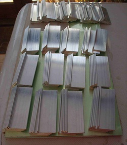 |
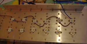
| Fins + Base The fins are bolted to the 500mm x 150mm base plate of 1/8" Aluminium - I got a 2m long plate & then cut it into 4 base plates. To enable me to mount a cover over the fins to provide an air channel for the fan, I used 2" x 0.5" angle as 'sides' which can be seen on the left of the 1st fin. Another question I had was - how to connect the fins to the base plate? I could use aluminium rivets or nuts & bolts. Another web site had a paper on the spacing of rivets / bolts to give a good contact, this suggested that a 2" spacing was OK. I used stainless M3 nuts / bolts & washers. | 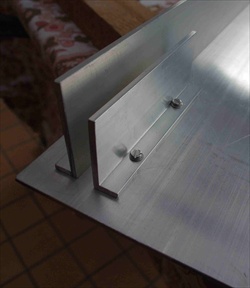 |
Thermal Paste Even though the fins are bolted to the base plate, any air trapped in the gap will act as an insulator. To ensure the fins make a good thermal contact I used thermal grease between them. Arctic Silver 5 seems to be the best paste, so that is what I used! It is usually used for microprocessor heat sinks in PCs. | 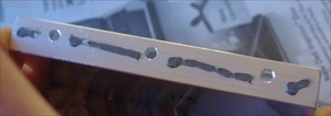 |
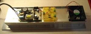
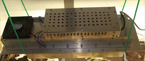
Fan cover Here you can see the 1st grow light with all its fins attached, the two side angle strips and the green cover which will go over the fins. The hole is where the fan will extract air out from the fins, the air will enter the fins from the left. You can also see the offset fins to increase air flow, hence cooling. | 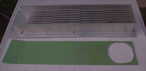 |
| Constant current circuit Each set of 6 LEDs requires a constant current circuit. Here can be seen the two circuits for one light. When I first tested the lights I had forgotten the power dissipated in the constant current source chip. So it overheated and failed - a worrying moment till I worked out the problem! I then added the black heat sinks to keep the chips cool. | 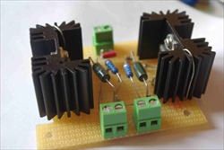 |